
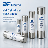
DF Electric aM Cylindrical Fuse Links: Sizes, Specifications and Selection Guide
Published by Automation24 Technical Team on 11th Oct 2026
Introduction to DF Electric aM Cylindrical Fuse Links
DF Electric aM cylindrical fuse links are designed for short-circuit protection in motor circuits, transformers and other electrical loads with high inrush currents. Their current-limiting characteristics and low pre-arcing I²t values help reduce the electrical stress placed on downstream equipment, including contactors and other switching components.
The aM utilization category is intended for short-circuit protection. It does not provide full-range overload protection on its own, so an appropriate overload protection device, such as a thermal overload relay or an equivalent device, must be used in combination with the fuse link.
DF Electric offers cylindrical aM fuse links in four principal sizes: 8×32 mm, 10×38 mm, 14×51 mm and 22×58 mm. Depending on the size and rated current, the range includes versions without a visual indicator, versions with a visual fusing indicator, and selected versions with a striker for compatible fuse holders equipped with a microswitch.
This guide explains the main differences between these sizes, their technical characteristics, available configurations and the key factors to consider when selecting an aM fuse link for an industrial application.
What Is an aM Fuse and How Does It Work?
The aM designation identifies a fuse utilization category commonly used in motor circuits. These fuse links are designed primarily to interrupt short-circuit currents while accommodating the high starting currents associated with motors and similar loads.
During motor starting, the current may temporarily rise above the normal operating current. Fuse selection must account for this starting behaviour while still providing appropriate short-circuit protection.
Unlike a full-range fuse, an aM fuse link is not intended to provide complete protection against overloads. A separate overload protection device is therefore required to protect the motor and installation against sustained overcurrent conditions.
Correct protection depends on the coordination of the fuse link with the motor, contactor, overload relay, conductors and other circuit components. The fuse should not be selected solely by matching its rated current to the motor's nominal current.
Available Sizes and Main Specifications
DF Electric's cylindrical aM fuse-link range covers four principal body sizes. The applicable current ratings, voltage ratings, breaking capacities and available configurations depend on the selected size and product reference.
| Fuse size | Rated-current range | Rated voltage options | Rated breaking capacity |
|---|---|---|---|
| 8×32 mm | 1–10 A | 400 V AC | 120 kA at 400 V |
| 10×38 mm | 0.16–32 A | 500 V AC and 400 V AC | 120 kA at the specified voltage |
| 14×51 mm | 0.25–50 A | 690 V AC, 500 V AC and 400 V AC | 80 kA at 690 V; 120 kA at 500/400 V |
| 22×58 mm | 2–125 A | 690 V AC, 500 V AC and 400 V AC | 80 kA at 690 V; 120 kA at 500/400 V |
Important: Not every rated current is available at every voltage. The applicable voltage, breaking capacity and ordering reference must be confirmed in the manufacturer's datasheet for the exact fuse rating.
8×32 mm aM Fuse Links
The 8×32 mm range is intended for lower-current applications and is rated for 400 V AC. DF Electric lists rated currents from 1 A to 10 A, with standard versions and visual-indicator options available for selected ratings.
The manufacturer's datasheet specifies a rated breaking capacity of 120 kA at 400 V AC. The physical dimensions listed in the datasheet are approximately 8.5 mm in diameter and 31.5 mm in length.
Download the official DF Electric 8×32 mm aM datasheet
10×38 mm aM Fuse Links
The 10×38 mm range covers rated currents from 0.16 A to 32 A. DF Electric specifies 500 V AC and 400 V AC ratings, depending on the selected current and reference.
Standard versions and versions with a visual fusing indicator are available for selected ratings. The manufacturer's datasheet lists a rated breaking capacity of 120 kA and dimensions of approximately 10.3 mm in diameter and 38 mm in length.
Download the official DF Electric 10×38 mm aM datasheet
14×51 mm aM Fuse Links
The 14×51 mm range covers rated currents from 0.25 A to 50 A. The manufacturer lists voltage ratings of 690 V AC, 500 V AC and 400 V AC, with the applicable rating and breaking capacity depending on the selected reference.
Available configurations include standard versions, versions with a visual fusing indicator and selected versions with a striker. Striker versions are intended for use with compatible fuse holders equipped with a microswitch.
The manufacturer's datasheet specifies a breaking capacity of 80 kA at 690 V AC and 120 kA at 500 V AC and 400 V AC. The listed physical dimensions are approximately 14.3 mm in diameter and 51 mm in length.
Download the official DF Electric 14×51 mm aM datasheet
22×58 mm aM Fuse Links
The 22×58 mm range covers rated currents from 2 A to 125 A. DF Electric lists voltage ratings of 690 V AC, 500 V AC and 400 V AC, with the applicable breaking capacity depending on the rated voltage.
Standard versions, visual-indicator versions and striker versions are listed for applicable references. The datasheet specifies a breaking capacity of 80 kA at 690 V AC and 120 kA at 500 V AC and 400 V AC.
The manufacturer marks the 125 A references as overrating fuse links. This designation is important and must be considered during selection. These references should not be treated as interchangeable with ordinary fuse ratings without checking the manufacturer's technical documentation and the requirements of the application.
The listed physical dimensions are approximately 22.2 mm in diameter and 58 mm in length.
Download the official DF Electric 22×58 mm aM datasheet
With Indicator, Without Indicator and With Striker
DF Electric cylindrical aM fuse links are available in different configurations depending on the fuse size, rated current and product reference.
Without Indicator
A fuse link without an indicator is the standard configuration without a visual fusing indication feature. Whether this version is suitable depends on the installation's maintenance and inspection requirements.
With Visual Indicator
A fuse link with a visual indicator provides a visual indication when the fuse has operated. This can help maintenance personnel identify an operated fuse during inspection.
Indicator availability depends on the fuse size and rated current. Always check the manufacturer's ordering table for the exact reference.
With Striker
Selected 14×51 mm and 22×58 mm aM fuse links are available with a striker. The striker is intended to operate with a compatible fuse holder equipped with a microswitch, allowing an electrical indication or control response when the fuse operates.
A visual indicator and a striker are different features. They should not be treated as interchangeable, and the compatibility of the fuse link, holder and monitoring circuit must be verified before installation.
Technical Specifications and Dimensions
When selecting a cylindrical aM fuse link, engineers should consider more than its physical size and rated current. The key parameters include:
-
Rated voltage and rated current
-
Rated breaking capacity
-
Physical dimensions and fuse-holder compatibility
-
Utilization category
-
Power dissipation
-
Pre-arcing I²t values
-
Time-current characteristics
-
Cut-off characteristics
-
Ambient-temperature derating
-
Visual indicator or striker configuration, where required
DF Electric's datasheets provide the technical information for each fuse size. Values such as power dissipation and I²t vary with rated current and, where specified, rated voltage. They should therefore be taken from the relevant datasheet rather than transferred from another fuse size or rating.
The manufacturer lists IEC/EN 60269-1 and IEC/EN 60269-2 among the applicable standards for the product range. Consult the current datasheet for the relevant product-specific information.
Power Dissipation, Temperature Derating and I²t Values
Power Dissipation
Power dissipation is the power converted into heat by a fuse link under the conditions specified by the manufacturer. It is an important consideration when designing fuse holders, enclosures and electrical assemblies.
Where multiple protective devices are installed close together, the combined heat generated by the devices and the enclosure's ability to dissipate heat should be considered. Use the power-dissipation value for the exact fuse size and rated current.
Power-dissipation values should not be assumed to be the same across different sizes or current ratings.
Ambient-Temperature Derating
DF Electric specifies an operating-temperature range of −40°C to 80°C and states that derating of the maximum current is necessary when the ambient temperature exceeds 25°C.
The manufacturer's derating table should be consulted when the fuse will operate above 25°C. The appropriate factor depends on the ambient temperature and must be applied in accordance with the manufacturer's instructions.
Temperature, enclosure conditions and the installation environment should all be considered when determining the appropriate fuse rating.
Pre-arcing I²t
Pre-arcing I²t represents the integral of current squared over the time up to the beginning of the fuse element's melting process. It is an important parameter in the assessment of short-circuit coordination and the energy let through before pre-arcing.
The manufacturer's tables distinguish pre-arcing I²t from I²t values associated with different rated voltages. These values should not be assumed to describe the same stage of fuse operation.
When comparing fuse links or coordinating protective devices, use the definitions and values supplied for the exact product reference. The detailed numerical values should be taken directly from the corresponding DF Electric datasheet.
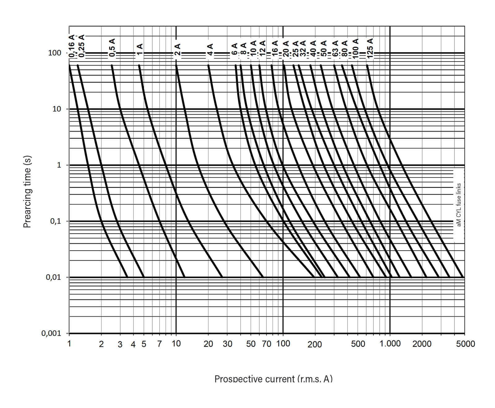
Time-Current and Cut-Off Characteristics
Time-Current Characteristics
A time-current characteristic shows the relationship between prospective current and the time associated with fuse operation. DF Electric's aM datasheets identify the plotted characteristic as pre-arcing time.
These curves help engineers assess fuse behaviour under different current conditions and support protection coordination. They must be interpreted using the axes, units and legend provided by the manufacturer.
Pre-arcing time should not be described as total clearing time unless the source explicitly identifies the curve as total clearing time. The two terms refer to different stages of fuse operation.
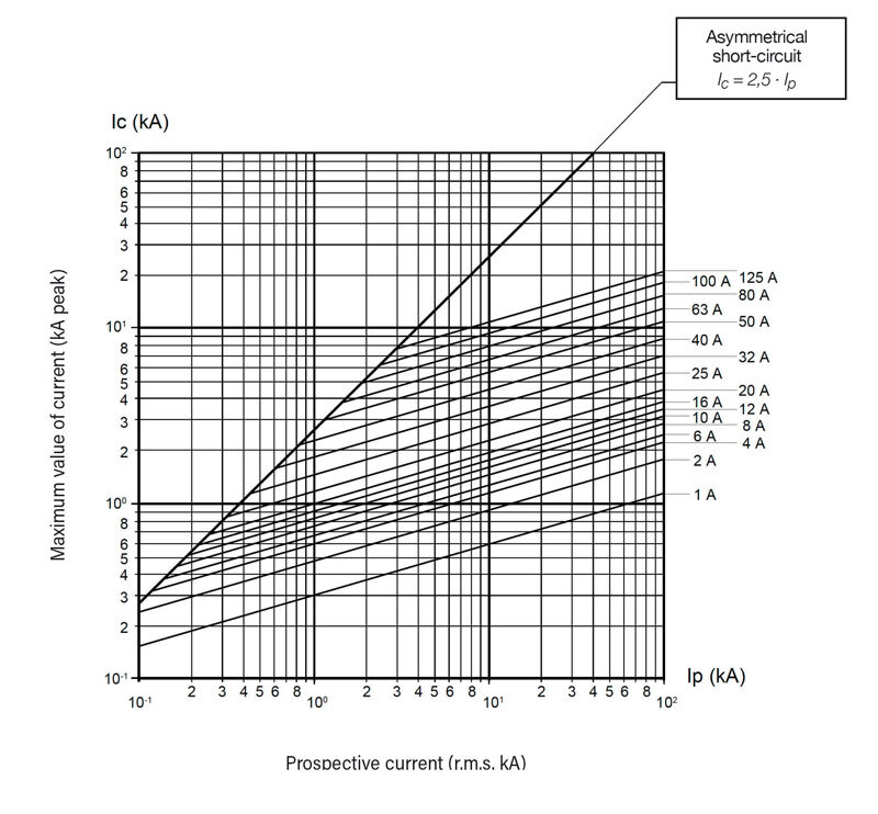
Cut-Off Characteristics
The cut-off characteristic relates the prospective short-circuit current to the maximum peak current let through by the fuse. This information helps engineers evaluate the peak-current stress imposed on downstream equipment during a short circuit.
The correct curve must be selected for the applicable fuse size and rated voltage. Curves from one size or rating should not be substituted for another without technical justification.
For engineering calculations and protection coordination, consult the original manufacturer's graph and the corresponding technical data.
How to Select the Right aM Fuse Link
Use the following steps as a starting point when selecting a DF Electric cylindrical aM fuse link.
-
Identify the application. Confirm that the aM utilization category is appropriate for the intended motor or other load circuit.
-
Determine the required rated current. Consider the load's operating current, starting characteristics and protection-coordination requirements.
-
Confirm the rated voltage. Select a fuse link suitable for the system voltage and verify that the specific current rating is available at that voltage.
-
Check the prospective short-circuit current. Confirm that the fuse link's rated breaking capacity is adequate for the installation.
-
Coordinate overload protection. Provide a suitable separate overload protection device, because an aM fuse link alone does not provide full-range overload protection.
-
Verify physical compatibility. Check the fuse dimensions and compatibility with the intended fuse holder or base.
-
Choose the required configuration. Confirm whether a standard version, visual indicator or striker is required and available for the selected reference.
-
Consider thermal conditions. Apply the manufacturer's ambient-temperature derating requirements where necessary.
-
Verify the ordering reference. Check the current datasheet for the exact rated current, voltage, breaking capacity, dimensions and configuration before ordering or installation.
Selection and coordination should be carried out by qualified personnel in accordance with the manufacturer's instructions and the applicable installation requirements.
Downloads and Technical References
The following official DF Electric documents provide detailed specifications, dimensions, ordering references, power-dissipation values, I²t data and characteristic curves for the relevant fuse sizes.
Final Note
Always verify the exact fuse reference, rated current, voltage, breaking capacity, dimensions and technical characteristics against the current manufacturer's documentation before selection or installation. Product specifications may be revised by the manufacturer.
For technical applications, installation and coordination must be assessed by qualified personnel in accordance with the manufacturer's instructions and applicable standards.